
Circuit 3: Bulbs In Series
This circuit illustrates what happens when you put additional resistance into the load component in series.
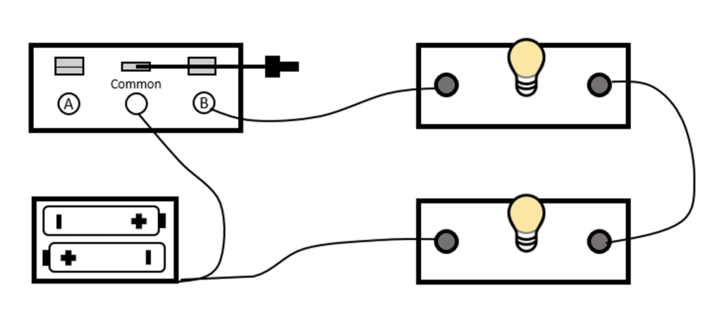
For this circuit, you will need the battery, one switch, and two sockets and lightbulbs.
Follow the video below to build this circuit on your own workbench.
video
Understanding This Circuit
Yay! You just made a circuit with two load devices in a series.
Notice: Something is different about the lightbulbs this time, compared to the previous circuit. What do you observe?
- Using your hand, with the switch closed so the lights are on, trace the path the electricity takes. Start at the battery and follow the path until you get back to the battery on the second lead.
- Using the multimeter, with the battery leads disconnected so there is no power to your circuit:
- Determine the resistance of each bulb by itself. Is it the same resistance you measured for one bulb in the earlier circuits? Record this finding.
- Determine the resistance of both bulbs together, when resistance is measured across them both (in series). Write this value down as well.
- How does the resistance of both bulbs compare to the resistance of only one bulb?
- Is it possible for just one of the lightbulbs to light if the second one is burned out? Why? Or why not? Test your hypothesis by removing one of the lightbulbs from the socket.
Feel like you've got this circuit mastered? Move to the next page and let's build another one.