
🧰 Project 3A: Serial Monitor with Potentiometer!
This Project is an Example of…
VOLUME KNOBS
If you’ve ever turned a dial to adjust the volume of your favorite song, you probably used a potentiometer to send a signal to a microcontroller to then change the audio output of a speaker! See what the microcontroller receives in the serial monitor.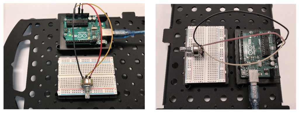
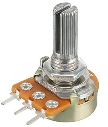
For this project we introduce a widely used component in electronics projects: the potentiometer. It is often called a "pot" for short by people who build electronics.
A dimmer switch to dim the lights found in many homes is an example of a potentiometer. A dimmer switch varies the amount of resistance it presents to electricity when you turn a dial, knob or screw on the potentiometer. More resistance lets less electric current through and the lights get dimmer; less resistance lets more current through and the lights get brighter.
By turning a dial all the way to the left (counter-clockwise) you increase the resistance in the potentiometer; all the way to the right (clockwise) decreases the resistance.
This project will read the resistance of a potentiometer several times a second and display the amount of resistance in a special window in the Arduino Web Editor.
What you will learn:
- You will learn how to set up and wire a potentiometer for use with an Arduino. Potentiometers have an amazing array of uses in electronics and electrical projects. We will build a few projects that use potentiometers in this course.
- You will also learn about the Serial Monitor in the Arduino Web Editor. The Serial Monitor is a powerful tool that lets us communicate with the Arduino. It is particularly useful because it can show us the values that the Arduino is getting from sensors or sending out to actuators that it is connected to.
- In the code, you will see a function that interprets the current setting of the potentiometer to a number within a range between 0 and 1023. This number can be used to make decisions based on what the pot is currently set to.
- In our program, the resistance of the pot is shown on the left after the word ANALOG.
- The program then used the resistance value of the pot to set a voltage between 0V and 5V, which is displayed on the same line after the word VOLTAGE.


Now that you've wired up a few projects, try to build this one just by looking at the diagram above.
Building Tips
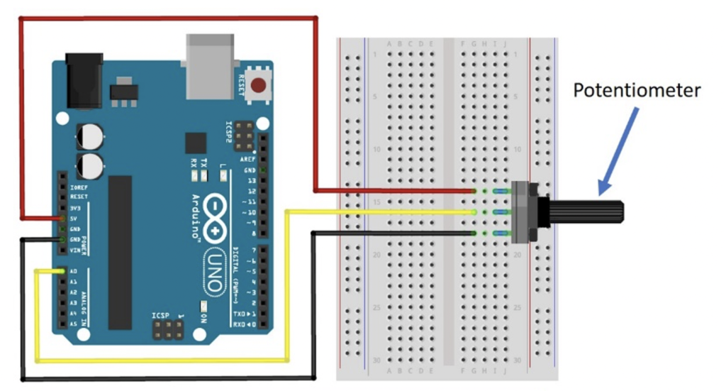
- Wire this project according to the Fritzing diagram for Project 3A.
- This is an easy project to wire up; we’ll use it as a basis for more complicated, interesting projects to come.
- IMPORTANT: Make sure to plug the long color jumper wire to the CENTER lead of the potentiometer.
- The other end of the color jumper wire goes to Analog Pin A0 on the Arduino.
- Double-check your connections before powering up, especially the power connections.
- UPLOAD AND SAVE the correct/current sketch to your Arduino from the Web Editor.
- SOMETHING NEW: Turn on your Serial Monitor when you start this project. On the left-side menu (under EDITOR), click the fourth menu option from the top that says MONITOR.
This will open a long vertical window that will show you feedback from the Arduino.
Expand Your Learning
Experiment with the potentiometer by turning the dial up and down.
- Leave it low for a while and see what happens.
- Leave it high for a while; now what happens.
- Turn the potentiometer slowly; what happens to the values you are seeing on the Serial Monitor?
- What is the lowest number it reads? What is the highest number?
- Does the lowest number come when you turn the dial down/left/CCW?
- Think of some ways you could use this potentiometer. Where do you see potentiometers in real life?