
🧰 Project 3B: Arduino Flash Rate Controlled by Potentiometer!
⚠️ WARNING! ⚠️
This project contains flashing lights which may not be suitable for people with photosensitive epilepsy.This Project is an Example of…
STROBE LIGHTS
Stroboscopes produce a continuous series of short, flashing lights and have uses that from range from studying the behavior of heavy rotating machinery and photographing fast-moving objects.NOTE!
This project uses the same Fritzing diagram as Project 3A but uses a different code.Now that we have introduced the concept and function of the potentiometer, let's put it to use and control something in real life.
As you recall, the Arduino has an onboard LED that is connected to Digital Pin 13. We controlled it using a program in Project 1D.
Let's use this LED as an output device controlled by our potentiometer. We don't have to change any wiring whatsoever from our last project; we just need to send a new program to our Arduino--that is, reflash the Arduino.
When we do, you will be able to control the rate at which the onboard LED flashes using the potentiometer.
What you will learn:
- Using the wiring exactly as we set it up for the last project, you will see a simple but effective demonstration of how to use a potentiometer in real life.
- This is also a good demonstration of taking advantage of the easy-to-use onboard LED to get feedback for different projects. It's fast and easy—no wiring needed.
- Like before, turning the pot all the way down/left/CCW will make the time interval for the flashing very short, so the light blinks faster and faster. Turning the pot up/right/CW will make the interval much longer (making the light blink slower).
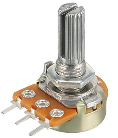
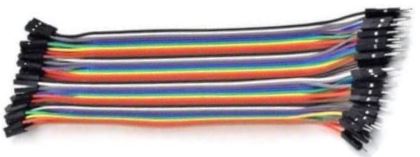
Required Components


Add Sketch to Editor
Download the Sketch
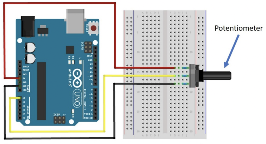
Fritzing Diagram
Building Tips
- You don’t need to make any wiring changes from the previous project (Project 3A), so if you just did that one, don’t change anything.
- If you are coming at this project fresh, wire it according to the diagram for Project 3B.
- IMPORTANT: Make sure to plug the long color jumper wire to the CENTER lead of the potentiometer.
- The other end of the color jumper wire goes to Analog Pin A0 on the Arduino.
- Double-check your connections before powering up, especially the power connections.
- UPLOAD AND SAVE the correct/current sketch to your Arduino from the Web Editor.
- NOTE: This project does not use the Serial Monitor, so if that’s not working, it’s because this program doesn’t include that functionality.
Expand Your Learning
Experiment with the potentiometer by turning the dial up and down.
- Leave it low for a while and see what happens.
- Leave it high for a while; now what happens.
Think of other things you could control with the potentiometer.