⛰️ What’s Resistance?
Now you have three out of four key concepts in your understanding of electrical concepts: charge (C), amperage (A) and voltage (V). Let’s get the last piece of the puzzle.
Let’s say you finally finished showering, got dressed and stepped outside to wash your electric Soul/Leaf/Tesla before heading off to meet your friends. Just as you’re spraying down the car for its final rinse, the water stops flowing like somebody stepped on the hose. What? Again?!?

Getty Images
You spin around, and that’s it—somebody DID step on the hose! Annoying little brother better run fast, because as soon as the pressure comes back….
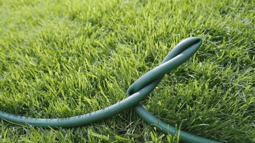
Which means that you also know the concept of resistance from your day-to-day experience with flowing water. We’ve all folded a garden hose over and clamped it with our hand to slow down the flow when full-blast was too much. We know that we can control how fast the water comes out of the end of the hose by increasing the resistance before it gets to the end.
Let’s rerun our water tank experiment again, but make one key change: let’s put in a much smaller pipe between the tanks. This time, watch the clock carefully to see what happens.
What did you observe?
- We started with the same amount of water in each tank (20 gals vs. 0 gals), and we opened the valve.
- Because the pipe was so much smaller, it took 5 seconds to reach equilibrium, where before it only took 2 seconds.
- That means that our flow rate went from 5 gallons per second down to 2 gallons per second, all because of the increased resistance of the smaller pipe.
- Notice that the pressures in the tank didn’t change—either at the beginning or the end of the experiment.
- And this is what we would experience with the garden hose: if we add resistance by squeezing the hose somehow, less water comes out every second. We have slowed down the gallons per minute by adding resistance.
We have the same concept with electricity. Interestingly, there aren’t really units of measure for resistance in the flow of water (not any that are used in daily life), but there is a way to measure resistance in an electrical circuit.
We are interested in resistance because almost every component in a circuit that performs “work” will present some resistance to the flow of electricity. Some examples of work done by electricity include converting it into light (using a bulb); creating sound (via a speaker); creating heat (with a heating element); or creating motion (by using a motor).
In our animation, almost all the resistance in the circuit comes from the light bulb, which creates light as electricity passes through the filament. Almost no resistance comes from the switch, the wires or the ammeter, which are very low-resistance conductors. In order to create more resistance in our experiment, we can add another light bulb into the circuit and see what happens.
Let’s set up our electrical experiment one more time, but with two light bulbs in a row.
What did you observe?
- When we turn the switch on, both light bulbs start to glow. However, they are only one fourth as bright as before.
- Look closely at the ammeter. What does it say?
- Do you remember what it said in the last experiment, with only one bulb? That showed 1 full amp of current; now, it’s only half that much.
- Did the voltage change? (No; it’s still the same.)
- But watch the stopwatch. Before, with one bulb, it took 4 seconds to move 4 coulombs of charge in the battery, from the positive end at high potential, through the light bulb and into the negative end with lower potential.
- Now, with two bulbs, it takes 8 seconds to move the same amount of charge.
To Summarize
With the same voltage (pressure), we get...
...one fourth as much light from each bulb, but...
...for twice as long. Why is this?
Much like the smaller pipe in our water tank illustration, increased resistance in an electrical circuit reduces the amount of current that can be pushed through that circuit for a given voltage. The same pressure with increased resistance gives us a lower flow rate.
The units we use to measure resistance to electric current are called ohms. And you guessed correctly—we have a gauge to measure them, and it’s called an ohmmeter. The symbol for ohms is the Greek letter omega, which looks like this: Ω. When you see that symbol, just pronounce it as “ohms.”
Unlike the other two gauges you’ve learned about, we don’t use ohmmeters while there is current present. NEVER check resistance while current is flowing in a circuit—it can be dangerous to you, and will probably damage or destroy the ohmmeter.
Let’s run that last animation again to see how an ohmmeter can help explain what we observed with our two-bulb circuit.
🌟 KEY CONCEPTS
- Resistance is the tendency for a component in a circuit to try to restrict electric current from flowing through that component.
- The unit of measurement for resistance is ohms.
- Omega (Ω) is the abbreviation for ohms.
- The instrument used to measure resistance is the ohmmeter.
- Ohmmeters are connected across the component you are measuring for resistance, always with the power OFF in a circuit.
