
🔧 Step 3: Attaching the PCBs and Rear Wheels
Estimated time: 20 mins
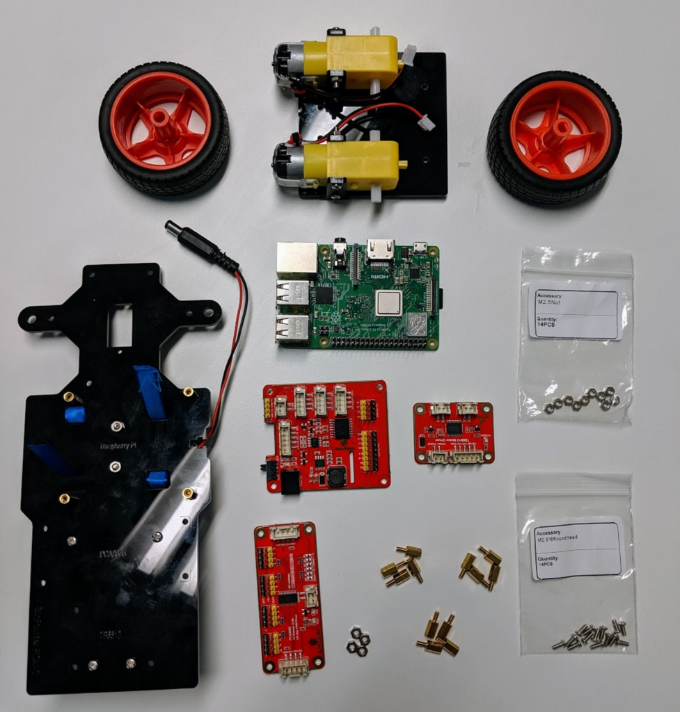
Okay! We are going to attach all of the PiCar circuit boards (PCBs) that make the car function.
Here is what we’ll need:
Note: If you have the flat, non-tabbed chassis version, you will secure the boards with twelve M2.5×6 screws onto the copper standoffs. You will not use M2.5×12 screws since you have the extra standoffs. The orientations will be the same.
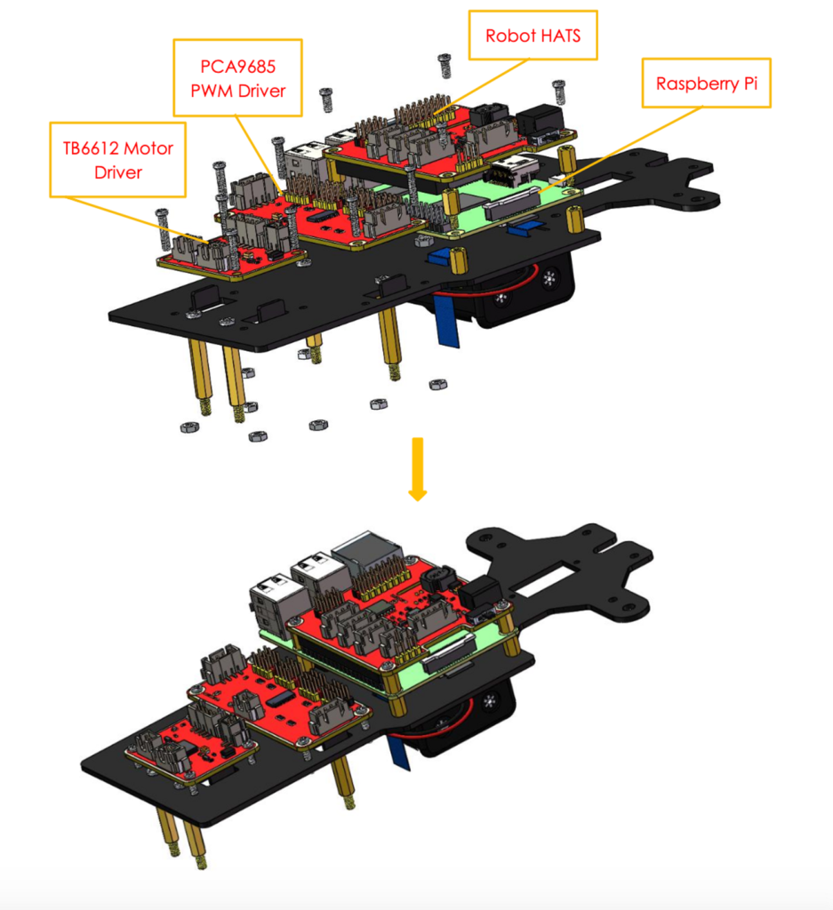
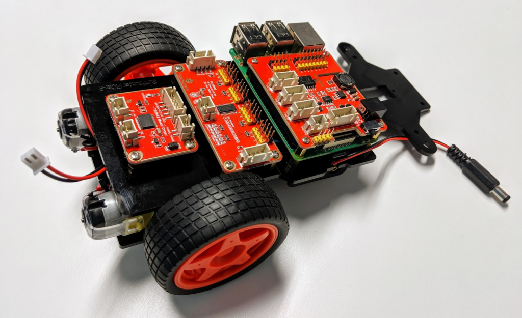
First, grab the Raspberry Pi single board out of its box and place it onto the four M2.5×8 copper standoffs you previously inserted on the middle of the board. You’ll see holes on the corners of the Pi board that correspond with the holes on the upper chassis plate.
Next, screw four more M2.5×8 copper standoffs in on top of the first four standoffs you used to seat the Pi onto the upper chassis plate. These upper four standoffs will secure the Pi and will become the base for the Robot HAT board.
The Robot HAT board is the largest red board in your kit. Screw it onto your Pi as shown. Attach the Robot HAT board with four M2.5×6 screws. These will screw right into the standoffs in some kits. In others, you will have extra gold standoffs to use instead.
Now, get the PCA9685 PWM board from your box. It should be the red board that is as wide as the upper chassis plate. Screw it in with four M2.5×12 screws and four M2.5 nuts right next to the Raspberry Pi.
Finally, find the smallest and last red board, which is called a TB6612 Motor Driver. Use four more M2.5×12 screws and four M2.5 nuts to attach it to the back area of the upper plate.
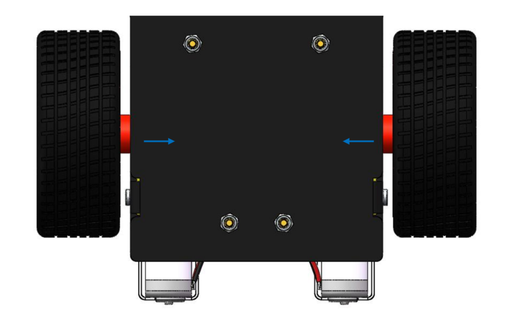
Use four M3 nuts to attach the back wheels to the copper standoffs in the upper chassis plate.
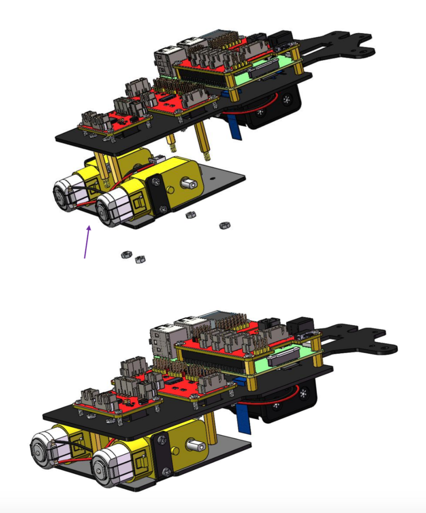
Note: For the non-tabbed chassis version, your completed set up so far will look like this:
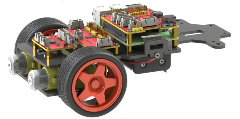
Stick the rear wheels onto the motors as shown. Note that the rear wheels look different from the front wheels (go back to the materials list page to spot the difference). Rotate them a bit to ensure they spin.
Pro tip: you can use some superglue to firmly affix these wheels to the motors for more reliability but this step is optional.
On to Step 4!