🔧 Step 3: Attaching the PCBs
The next step is to attach the Printed Circuit Boards (PCBs) that make the car function. Here is what we will need:
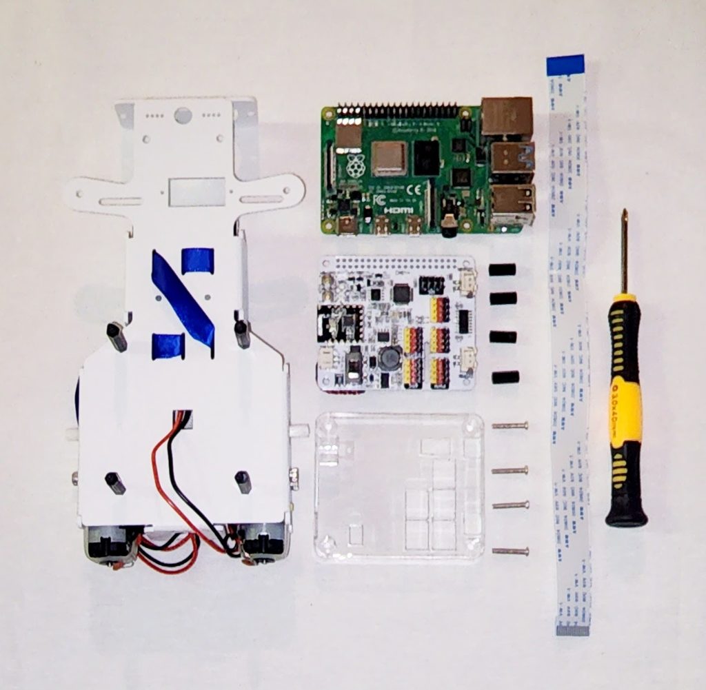
Attach the PCBs
First, grab the Raspberry Pi single board out of its box and place it onto the four M2.5x20+6 standoffs you previously installed on the board. You’ll see holes on the corners of the Pi board that correspond with the holes on the chassis plate. The USB and ethernet ports should be faced toward the back of the chassis plate, close to the motor wires.
Next, insert the FFC cable into the ribbon cable slot on the Pi as shown. Gently pull up the black tab, insert the FFC cable, and push to close.
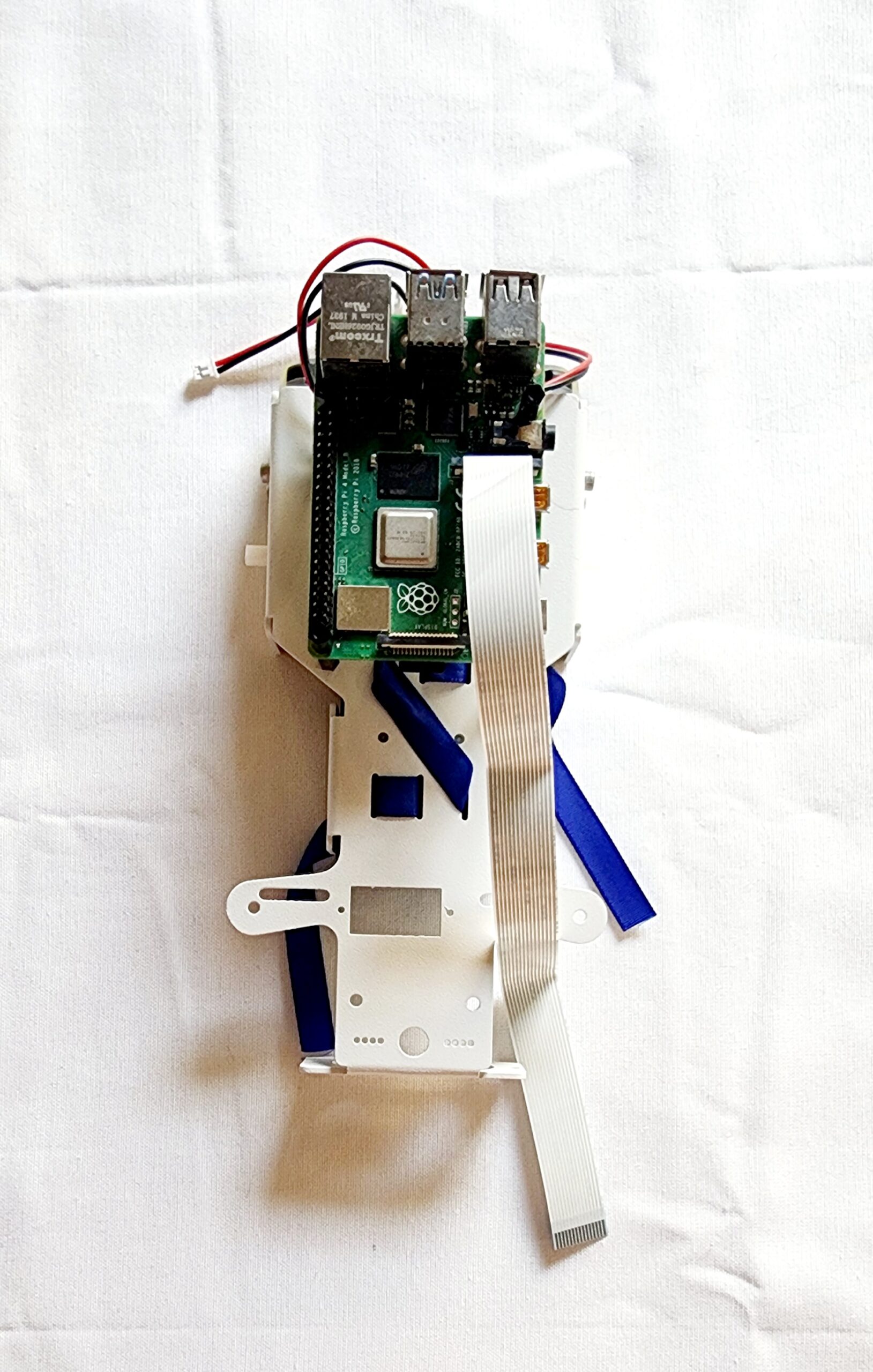
Face the other end of the FFC Cable toward the front of the chassis plate. We will attach it in a future step.
Next, screw four M2.5x11 standoffs on top of the first four standoffs you used to seat the Pi onto the chassis plate. These upper four standoffs will secure the Pi and will become the base for the Robot HAT board.
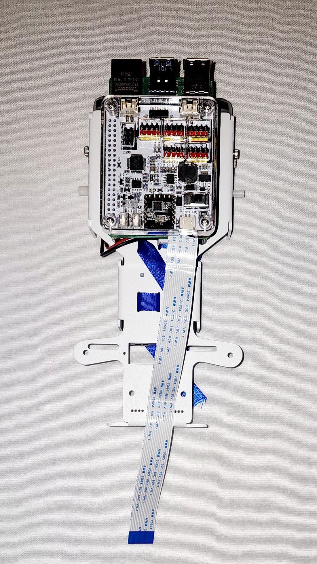
The Robot HAT board is the white board. Place it on top of the four standoffs you just added and place the Robot HAT Case on top of it.
Finally, use four M2.5x14 screws to attach the Case to the HAT.